Porcelain Insulator News
by Jack H. Tod
Reprinted from "INSULATORS - Crown Jewels of the Wire", September 1978, page 21
Matt Grayson (Roslyn, N.Y.) recently sent advertising information on
the pin
type insulators being manufactured and sold by Hendrix Wire & Cable Corp.,
Milford,
N.H.
I subsequently received from the company data sheets and insulator
specimens for use in making this fairly detailed report on them. As far as I can
recall, we haven't reported these insulators in Crown Jewels before.
These
insulators are made of high-density polyethylene. Hendrix started making the
plain top versions (next page) in approximately 1970 and, after some design
changes and improvements, there are now four models of these. Starting approximately one year ago, there are four models of the Vise-Top insulators (later
page). All data, drawings and photos are courtesy of Hendrix Wire & Cable
Corp,, and for which we thank them very much.
Unless you pick up one of these
in your hand, they are identical in appearance to sky-glaze porcelains except
for a surface which is comparatively only semi-glossy. The most striking feature
is their lightness in weight (about 1/3 That of comparably rated porcelains).
You will not recognize one of these polyethylene units on a pole top except for
their outlines differing from current porcelain styles. Each unit is marked
circularly around the small base surrounding the pin hole cavity with "H.
W. & C. CORP.", The catalog number (ie. "HPI 15-B"), and several
factory code numbers, one of which appears to be the year of manufacture.
These
insulators were originally developed as a result of research studies of
component materials for use on Hendrix Aerial Cable Systems. The company
technical papers explain all this fully, but I won't bore you with the technical
part of this which engineers can best cope with. In essence, the design solves
an old problem of the erosion of cable insulation when insulated cables were
mounted on porcelain insulators -- usually necessitating the removal of cable
insulation at each point where cables were tied to the insulators. The
polyethylene insulator has a low dielectric constant which is more nearly equal
that of the cable insulation, whereas the high dielectric constant of porcelain
insulators in comparison to that of the cable insulation causes an electrical
over-stressing of the latter. The use of the more compatible materials
also essentially eliminates the radio interference problems associated with this
overstressing of the cable-to-insulator interface. Needless to say, the
insulators are also very suitable for use with bare conductors, and they meet
the A. N. S .I. requirements for radio-free insulators.

Large Image (225 Kb)
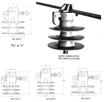
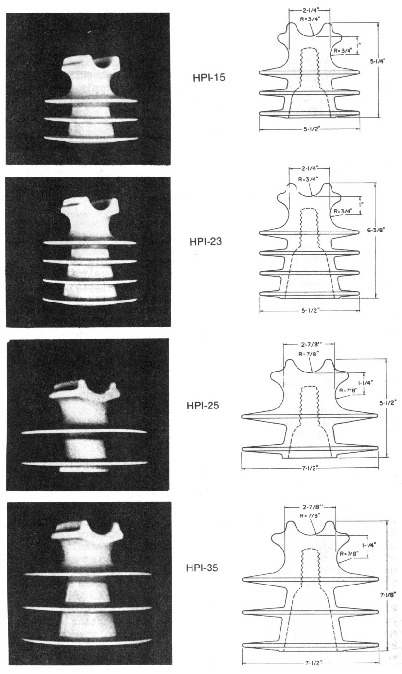
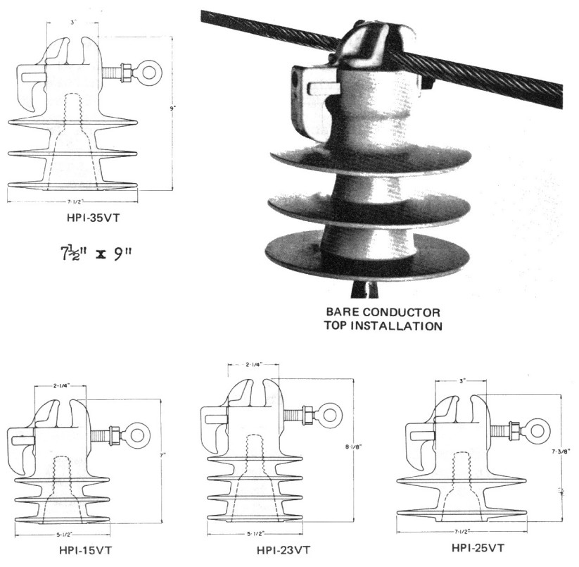
The drawings and cuts on the preceding page illustrate the plain top styles.
The HPI-15, 23, 25 and 35 styles are rated respectively at 15 Kv, 25 Kv, 25 Kv
and 35 Kv. The latter two are also available with 1-3/8" pin hole, numbered
as the HPI-25L and HPI-35L. Crowns will accept preformed tie wires.
The Vise-Top units shown below on this page are very interesting items as
compared with clamp tops on porcelain pin types. Note the clasp is formed directly
in the crown of the insulator, all parts being of the same polyethylene. The
side hook of the clasp may be used for cornering positions or for horizontal
insulator mounts. The sample of the HPI-15VT (Vise-Top) received is not
identical with the HPI-15VT drawing but has a deeper and curved side groove more
like the photo and drawing of the HPI-15 plain top style.
Large Image (105 Kb)
Even for a 1-1/2" diameter cable, the clamping screw threads are engaged
at least 2". When the clamp is tightened, it is locked in place by two
detent teeth integral with the head of the clamping bolt and which bite into the
insulator crown in an irrevocable manner, The conductor is clasped by tightening
the torque bolt with a hand tool or hot stick until the ring on the end of the
bolt breaks away.
There are several byproducts of the polyethylene design which are
advantageous. First of all, the lightness in weight simplifies packing,
shipping, storage and installation. Secondly, they are essentially
indestructible in normal use, and they can be properly grouped with other forms
of vandal-proof insulators. The company furnished photos and test data on
specimens which had been mercilessly punished with shots from high-powered
rifles, buck shot, shotgun rifled slugs. I'm sure you could threw rocks and
bricks at these from 10' all day without damaging one of them to the point where
they would become unserviceable.
The sample Hendrix insulators and various data sheets were (by the time you
read this) exhibited for everyone to handle and inspect at the NIA convention at
Reno in July. Guess we should all be "looking up" during our travels
so we'll have a chance to see these new items in action. Once again, many thanks
to Matt Grayson for steering us onto this report and to Hendrix Wire & Cable
Corp. for graciously furnishing us with the information and samples for the
report and exhibit.

Scott Given (Lodi, Ohio) received letter confirmation from Ohio Brass
Company that they use the new O-B logo on only new lines of items and that means
not on pin type insulators.
Dear Jack:
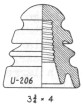
I recently found a U-206 transposition insulator on an old series street
lighting circuit the power company was taking down. The circuit has been in
service for at least 50 years. The insulator is a dark brown or black, has no
markings on it, and looks very crudely made. I was wondering if you might have
any clues as to when it was manufactured, or its manufacturer.
Marvin Suggs
Port Arthur, Texas
- - - - - - - - - -
Dear Marvin:
The U-206 originated with Ohio Brass Co. and was first cataloged by them in
1912. An engineering notice (unfortunately undated) indicates this item was
subsequently discontinued from manufacture, but it was still in the 1919 O-B
catalog.
The earlier version was U-206A with a shorter skirt and a much bulkier crown
portion and with a very heavy O-B embossed on the edge of the crown. These exist
with a light, bluish-gray glaze in addition to the mahogany browns.
Later versions are U-206, known to me only in various brown glazes which run
to the extreme of essentially black. These have an O-B embossed marking on side
of the top crown portion, but this can be faint to undetectable at times.
Westinghouse in the 1920's continued on with Pittsburg's styles (U-202
transposition) but by 1939 had adopted one transposition approximating the
U-206. It has a much smaller and flatter top crown portion than did the O-B
ones, and my specimen is an unmistakable dark chocolate brown glaze and with a
prominent incuse Westinghouse marking on the skirt.
Putting all the above facts together indicates that May wheat will probably
go to 345 and that you have an O-B tramp of about 1920 vintage.
Jack

Dear Jack:
... Also, does the marking of the U-441 Fred M. Locke effect the $80
value you have in your book? If so, which marking is most desirable?
John & Karen Sanville
Broomfield, Colo.
- - - - - - - - - -
Dear John & Karen:
The listed U-441 value is based on any marking showing it to be a Fred
M. Locke item. Even though we know these were made in the Fred Locke era at
Victor, an unmarked one would be drastically deflated in value.
Jack
Matt Grayson (Roslyn, N.Y.) has for quite some time been using his
spare time away from his college studies to methodically go through the old
Journals of the American Institute of Electrical Engineers (AIEE). He's
concentrated on the particular years which might give answers to questions we've
had on early porcelain and glass insulators. He has recently sent a large stack
of prints of AIEE articles which potentially have new information, and here's a
sample.
In one period (roughly 1903), there were numerous meetings and seminars dealing
with the problem of burning (charring) of the wooden insulator pins just below
the insulators. The point of interest to me was that this was evidently a
serious and widespread problem, whereas I previously thought maybe they were
just overplaying it in the ads promoting use of the porcelain-based pins and the
steel pins
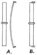
Mr. Etheridge was an active participant in these discussions, so it is not
surprising that Etheridge insulators and their steel pins were pictured and
described several times. Since I never had the full Etheridge patent of 6-25-01,
this was the first time I found out just how the pin system worked on it. I've
sketched at the right what the pin and spring insert looked like (A) and what it
looked like with the spring in place (Figure B). The following is Etheridge's
own description of its use:
"... It consists of a malleable iron tube 1-7/16" outside diameter
and 1-1/8" inside diameter. On the outside of this tube-pin is cast a
shoulder on which it rests when placed in the cross-arm. To lock this tube-pin
to the cross-arm a flat high-carbon steel spring -- on each end of which is
formed a gib -- is driven through the pin until the bottom end springs out over
the bottom end of the pin and cross-arm.
"The insulator, which has a plain hole to receive the pin, and a recess
at the bottom of the hole to receive the top gib of the spring, is then forced
down over the pin until the top gib springs out into the recess in the
insulator. This combination very securely locks the insulator to the pin and the
pin to the cross-arm; to unlock, place a screw-driver between the lower gib and
the pin, force the gib back and drive the spring out through the pin
again."
I doubt that anyone will ever find an Etheridge pin from bygone days, but
this description should make it possible for those who have Etheridge insulators
to make a pin and spring from scrap materials to complete their display.
One article of 6-30-98 concerned high-tension insulators in various systems
and testing applications in the field, and it came close to hitting the jackpot
for info on a couple of insulators -- glass and porcelain.
One test line was in Telluride, Colorado On a transmission line of 2-1/4
miles length, and a direct quotation from the test report indicates even tests
were in progress from December 1895 through mid-1896 and later. The line used
two glass insulator styles and one porcelain insulator style on the
double-circuit, three-phase line (6 insulators total per pole). The actual poles
are shown in one picture, plus a close-up of each insulator style with the
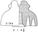
dimensions drawn in for each insulator.
Guess what the porcelain one was ---- Wow, the U-744. We have never been able
to attribute this early style to any manufacturer, but I have on numerous
occasions said I thought it most certainly was made by either Peru Electric Mfg
Co. or G.E. (Schenectady) before the era of Imperial-Locke-Thomas
insulators. The 1895-1896 dates of the Telluride tests with this insulator seem
to indicate I was on the right wavelength.
Now, guess what the two glass styles were. Well, the CD-287 for one (Ho-hum)
but ------ Wow, again, the CD-244 for the other one. That might be new info for
a lucky owner of an SCA specimen of CD-244. In case any of the rest of you want
to prospect for more of these jewels, the 2-1/4 mile line ran from the old power
station near Ames (a few miles from Telluride) to the Gold King mill. In event
you live in California and want to do your prospecting there, they said,
"The large glass insulator [CD-244] is the same as that used on the circuit
in the San Bernardino and Pomona plant."
It may be of interest to some that the tests for several days in December
1895 were with 25 Kv and 33 Kv. This was then increased to 45 Kv for one
continuous week in January 1896, and then to 50 Kv for a continuous run of 37
days in March 1896! Although the voltages were probably elevated so high only
for the purpose of the "testing", I think most utility people today
would say you were nuts if you told them a line with 62 poles of CD-287
insulators was operated at 50 Kv at that altitude and with all that rain and
snow.
Another report of 2-26-04 concerned construction practices on European
transmission lines, and there were several interesting points.
The Europeans considered The U.S. porcelain insulators quite inferior to
European units. Some U.S. shipments were totally rejected piece-by-piece by the
inspector for visual defects -- even though the insulators were o.k.
electrically. They had an aversion to accepting glazewelds or cemented
multiparts because they felt the individual pieces had to be tested separately
to locate defectives. They preferred to test all the parts and then assemble
them in the field.
They cemented insulators to pins and noted, "no attempt is ever made
here to use threaded insulators, as it is difficult to obtain good insulators
with thread of the exact gauge."
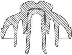
Various insulators were pictured in the article, and I had quite a surprise
when turning a page and seeing the one pictured at the right. (By scaling a
metric dimension shown for the height of the central part, it gave the
insulator's diameter as about 7-1/2".) The crown shape was typical of other
insulators shown.
If you'll dig out your copy of the November 1974 issue of Crown Jewels
and look on page 15, you'll see that we ran a report of the insulator pictured
at the left below. Note that the top shells of these two insulators are
essentially identical. Some variation could stem from the facts that the
insulator line drawings in the AIEE Journal were sometimes only fairly accurate,
and the California specimen was drawn from dimensioned sketches without it being
in hand here.
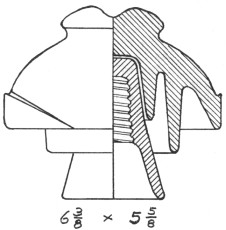
You see, I couldn't help but remember the 1974 report of the California
specimen, since I have always been very curious as to its origin. It was always
clouded in deep mystery, and I couldn't even find out who turned it up -- or
where it turned up first! It became even more firmly implanted in my memory when
I learned that it had subsequently traded hands at a San Diego insulator show
for the unbelievable price of $2500.00! That seems to me to be a helluva steep
price for an insulator when neither the seller or buyer knew anything about it
at the time -- its manufacturer, vintage, use, or whatever. I was told that the
agent of the anonymous buyer, after a series of very secretive phone calls, met
the buyer on a dark street corner where the insulator and cash finally changed
hands. Naturally we've heard nothing of the specimen since then.
Many thanks to Matt Grayson for all this info, and we'll have more coming on
it in upcoming issues.
| 
)
)
)
)
)
)
)